An Encoding Diagram Attempt
I tried to generate a diagram of the x86-64 legacy encoding based on what I know so far.
In the last post, we dove into the x86-64 binary we generated earlier, and figured out the encoding.
[ Check out all posts in “low-level” series here. ]
Recently, based on my limited (and possibly faulty) understanding, I drew an encoding diagram to help myself hand-decode x86-64. Today, I decided to share that diagram.
We will also test it with a few instruction variations. Hopefully, it will at least help someone build a minimal mental model.
Update [ 2024-01-08 ]: This post generated a super informative discussion on HN.
Addressing Modes
Understanding the complete encoding requires understanding all possible “addressing modes” used in x86 family, in detail. However, the nomenclature regarding addressing modes varies.
I am pretty much a newbie in assembly. So I rather avoid adding further to the confusion by trying to document addressing modes. I just skimmed this StackOverflow answer and this blog post, both look like good, detailed descriptions.
But I will mention a few “building block” terms to help read the diagram.
These three terms will show up in the SIB byte:
- Base: A base address stored in a register.
- Index: A, possibly scaled, numeric offset stored in a register.
- Scale: A scaling factor, scaling options being 1, 2, 4, and 8, stored in the instruction.
While at it, I also often encounter these terms that refer to static displacements encoded in the instruction:
- Absolute: Means there is a static address literally encoded in the instruction.
- Offset: Means there is a static numeric offset literally encoded in the instruction.
If you read up further on addressing modes, note that there are also cases where two addressing methods sound identical, while they are subtly different due to encoding limitations.
Encoding Diagram
Below is the diagram. It doesn’t document VEX encoding. This is just the legacy encoding with REX prefix. The ModR/M and SIB bytes are vertically placed (least-significant-bit being the top), to emphasize that REX byte “extends” the values stored of those bytes. Their actual placement in the instruction layout should also be clear
.
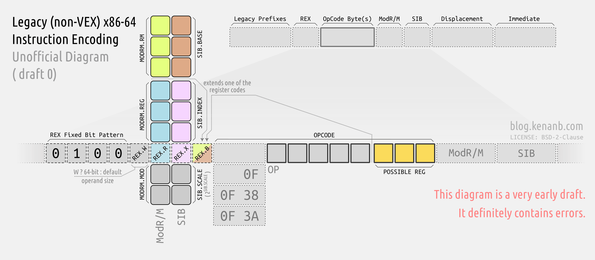
The source of this diagram is (and future iterations will be) available here in SVG form.1
Right click and open the image in new tab to see the diagram in full size.
Other Resources
Of course, this is inherently complicated. x86-only and simpler diagrams in Encoding Real x86 Instructions page are super useful for learning the layout without the added complexity of the REX prefix.
As usual, if you need reliable information on this, you should check out Intel’s Software Developer’s Manual and AMD’s AMD64 Architecture Programmer’s Manual volumes.
Update [ 2024-01-08 ]: The complete set of resources is being collected in a separate post.
Testing
Now, let’s start testing with an instruction, and make modifications based on the diagram.
We start with mov r8,rcx. If we assemble this, we get 49 89 c8.
The 4 (b0100) at the beginning matches the REX Fixed Bit Pattern.
The second byte is not 0F, so this instruction has a single-byte opcode. Therefore,89 is the opcode.
According to reference table, opcode 89 doesn’t store any register values itself. But it states that ModR/M.reg stores a register.
Therefore:
REX   : 49
OPCODE: 89
MODR/M: c8
Now that we know the overall instruction layout, let’s figure out the details.
REX Prefix
Looking at the REX byte (49) in binary:
0100 1001
We said 4 (0100) is the REX Fixed Bit Pattern. The remaining bits (1001) of the REX byte are:
REX.W: 1
REX.R: 0
REX.X: 0
REX.B: 1
REX.Wflag being set means the instruction uses 64 bit operands.REX.Bis going to extend some register code somewhere, effectively adding 8 to its value.
Since opcode doesn’t encode a register itself, and since there is no SIB byte, I guess it is ModR/M.rm being extended. (I am actually not sure if this reasoning is solid enough to cover all cases.)
It is easy to visually confirm if there is an “extended” register code, because it should show up as a register that has a numeric name pattern from R8* to R15* instead of something like RDX.
Remember, our original instruction was 49 89 c8, which is mov r8,rcx.
- We can see the effect of
REX.Wbeing set, as 64-bit registers are used. - If we disassemble the version that has
REX.Wunset (41 89 c8), we getmov r8d, ecxwhich has 32-bit register operands. - And if we toggle
REX.Binstead (48 89 c8), we getmov rax, rcx, which replacedr8withrax. Register code forraxis 0, and register code forr8is 8. - We can also try to toggle
REX.R, which is supposed to extend theModR/M.regslot. Disassembling4d 89 c8will give usmov r8, r9. So this time,rcxbecamer9. - Since there is no
SIBbyte, I assumeREX.Xdoesn’t have an impact for this instruction. (I am not sure if toggling that is valid or not.)
So the mystery of the REX is solved, and there is nothing to decode in the opcode itself.
We can move on to the ModR/M byte.
ModR/M Byte
We will split the ModR/M byte (c8) in binary form, into octal groups:
MOD:  11
REG: 001
RM : 000
The opcode already established that ModR/M.reg stores a register, not an opcode extension.
REX.R extends ModR/M.reg, but it is unset. So effective register code for ModR/M.reg is 1, which means rcx.
REX.B extends ModR/M.rm, and it is set. So effective register code for ModR/M.rm is 8, which means r8.
- If we bump
ModR/M.rmby 1 (49 89 c9), we getmov r9, rcx. - If we instead bump
ModR/M.regby 1 (49 89 d0), we getmov r8, rdx.
So the overall encoding looks like this:
          ____________________
         /                    \
0100 1001  10001001  11  001  (B)000
     |  |  MOV        | %RCX ,   %R8
     |  |             |
64-bit  extend        register addressing
        ModR/M.rm
The End
That’s it!
I think this is all I want to write about instruction encoding for a while. But I learned a lot in the process.
In the next post, I will share a list of resources that I found while writing these posts, and wrap this topic. But the “low-level” series will continue.
Thanks for reading!
-
I am not very experienced in assembly. If you find errors, please report in the blog’s Issues page. ↩